

Nitinol muscle wire is often demonstrated as a bare filament that contracts when current is applied. A production mechanism needs two terminations that carry load, deliver current, survive thermal cycling, and prevent local damage. Those joints frequently see the highest combined electrical, mechanical, and thermal stress in the system.
GEE SMA product notes list muscle wire as a compact actuator format for applications such as locks, camera switches, toys, and robotics. They list binary Ti-rich NiTi and Copper NiTi routes and Active Af options of 70, 90, 110, and 130 degrees C, subject to final specification. The selected muscle wire condition still needs a joint designed around its diameter, current, strain, and duty cycle.
The Joint Carries Current and Force at the Same Time
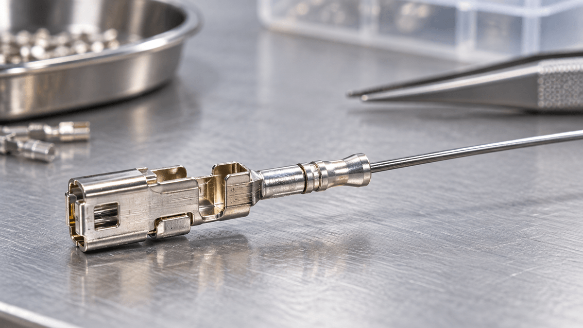
A termination with low electrical resistance can still damage the wire mechanically. A strong mechanical grip can still create unstable contact resistance and local heating. The design must satisfy both functions without nicking, sharply bending, crushing, or slipping the active element.
Crimps, swages, clamped tabs, and welded transitions each create different process risks. Soldering directly to NiTi is generally difficult and may require specialized surface preparation or an intermediate tab. Select the process through testing rather than assuming a conventional copper-wire method will transfer.
Keep Peak Strain Away From the Grip Edge
Abrupt stiffness changes concentrate bending and tensile strain at the point where the wire exits a rigid terminal. Add a controlled free length, smooth exit radius, compliant transition, or secondary strain relief. Prevent the wire from rubbing against a sharp housing edge during motion.
Inspect the highest-strain exit zone after cycling. GEE SMA's reset, strain, and heat controls are especially important here because an acceptable average strain can hide a damaging local peak.
Termination Resistance Can Create a Hot Spot
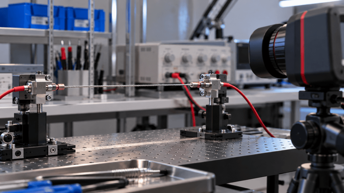
Joule heating is intended to occur along the active wire. Variable contact resistance at a crimp or clamp can overheat a short region, change the oxide, relax the joint, or damage adjacent polymers. Large metal terminals can create the opposite problem by acting as heat sinks and leaving inactive cold zones near each end.
Measure voltage drop across each joint and across the active length. Record current, resistance, and local temperature during representative cycles. Design the active length between thermal boundary zones instead of counting the full cut length as useful actuator length.
Preload Must Be Applied Without Twisting the Wire
Muscle wire usually operates against a bias spring, compliant structure, hanging load, or opposing SMA element. Assembly preload removes slack, but gripping and tensioning can add torsion or uneven load. Thin wire is particularly sensitive to handling marks and accidental kinks.
Use fixtures that control gauge length and tension while both terminals are secured. GEE SMA's return-path force balance helps set preload high enough for reset but low enough to preserve stroke and life.
Assembly Control Belongs in the Drawing
Define terminal material, surface finish, crimp geometry, tooling, force or displacement setting, number of crimps, exit orientation, free length, pull-test method, and permitted rework. Visual acceptance alone cannot confirm electrical contact or hidden wire damage.
Use sectioning, pull tests, resistance measurements, and thermal imaging during process development. GEE SMA's wire forming and surface controls reinforce the need to inspect after the assembly operation that can create the defect.
Terminal Materials Must Survive the Same Environment
Terminal alloy, plating, sleeve hardness, and housing material affect crimp retention, contact resistance, galvanic behavior, and heat flow. A soft sleeve may conform well but relax during thermal cycling. A hard edge may score the wire. Dissimilar metals can create environmental risks when moisture or salt is present.
Screen terminal combinations after humidity, temperature cycling, vibration, and any cleaning or sterilization process relevant to the product. Measure resistance before and after exposure, then perform pull and functional tests. Select plating and geometry from evidence on the complete joint rather than electrical conductivity alone.
Life Testing Should Separate Wire and Joint Failure
Monitor stroke, force, current, voltage, wire resistance, joint voltage drop, and endpoint drift during cycling. A rising joint voltage drop suggests contact degradation even if stroke remains acceptable. A stable joint with changing stroke points toward wire, load, or thermal-system changes.
After cycling, perform a pull test and inspect the wire exit, crimp interior, and heat-affected regions. GEE SMA's thermal-cycle stability checks provide a useful baseline for separating material drift from termination damage.
A Termination-Focused Prototype Plan
- Compare at least two feasible joint concepts using the production wire diameter.
- Measure pull strength, contact resistance, local heating, and initial stroke.
- Control active length, preload, exit radius, and assembly orientation.
- Cycle at minimum and maximum ambient conditions and expected duty cycle.
- Track joint voltage drop separately from total wire resistance.
- Inspect and section representative joints after life testing.
Nitinol muscle wire can provide quiet, compact linear motion, but the wire alone is not the actuator. Reliable products treat both terminations as engineered electromechanical components. A controlled joint protects the wire, stabilizes heating, preserves useful active length, and makes cycle-life results easier to interpret.