

A niti coil spring can magnify a modest material recovery strain into useful axial travel, but the drawing must define where that travel begins and ends. Free length alone cannot control the installed spring. Solid height, coil count, pitch, end geometry, guide condition, preload, and permitted strain determine whether the mechanism moves smoothly or damages the wire.
GEE SMA product notes distinguish shape-memory springs from room-temperature superelastic springs and identify compression, tension, open-coil, and closed-coil formats. The appropriate NiTi component route depends on whether temperature-driven motion or recoverable elastic force is the primary function.
Free Length Is Only the Uninstalled Reference
Free length records the spring without external load at a stated temperature. The product normally operates at an installed length with preload. A shape-memory spring may have different cold and hot free lengths, while a superelastic spring may show a nonlinear force response through its working travel.
Put cold and hot reference conditions on the drawing. GEE SMA's custom spring drawing controls help distinguish inspection geometry from the functional installed condition.
Solid Height Defines the Compression Limit
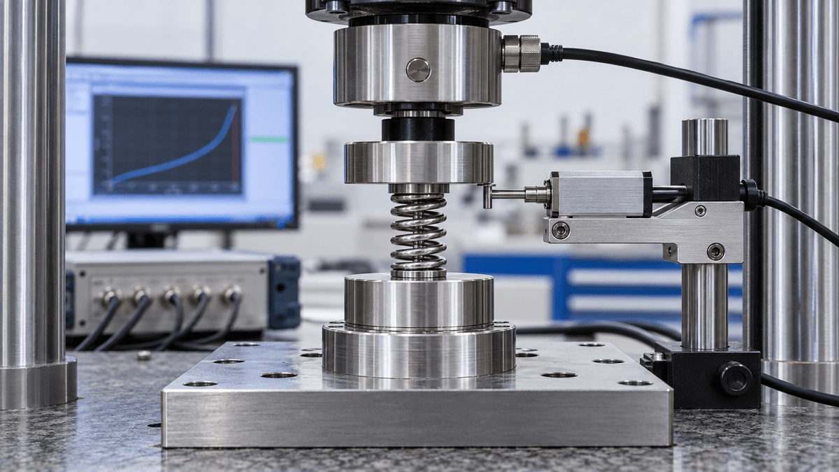
Solid height is the minimum axial length when adjacent coils contact. Repeated operation at or near coil bind raises local stress, creates contact wear, changes heating and cooling, and can permanently distort the ends. The mechanism should include travel margin before full solid height.
Specify maximum compressed length, permitted coil contact, stop location, and overload condition. For a tension spring, define maximum extended length and whether the body coils are initially closed. The stop should protect the spring without forcing current or thermal input to continue after motion ends.
Wire Diameter, Mean Diameter, and Coil Count Work Together
Wire diameter affects force, electrical resistance, thermal mass, and local strain. Mean coil diameter controls curvature and torsional strain. Active coil count changes spring rate and travel. Increasing stroke through geometry can reduce force margin or increase package length.
GEE SMA's stroke, geometry, and Af test plan connects dimensions to a measured load case rather than treating the coil as scaled conventional hardware.
Preload Determines the Installed Working Point
Preload removes clearance and sets the starting force against a valve, latch, slider, or bias spring. Too little preload permits backlash or incomplete engagement. Too much consumes available stroke and may prevent cold reset or overstrain the wire.
State installed length, preload force, assembly temperature, orientation, and tolerance stack. For opposing springs, plot both force-displacement curves in hot and cold conditions. GEE SMA's bias and return-path balance identifies where one element can reliably overcome the other.
Ends and Guidance Control Alignment
Closed, ground, hooked, straight, or custom ends change load transfer and active coil count. Compression springs with a large slenderness ratio may buckle without a guide rod or tube. Guidance can add friction and restrict heat transfer, so guide clearance and surface contact need testing.
Define end orientation, squareness, attachment method, guide diameter, permitted rubbing, and side-load limits. Inspect the transition between active coil and end feature because forming strain often concentrates there.
Stack the Spring Tolerances Inside the Mechanism
Wire diameter, mean coil diameter, active coil count, pitch, free length, end position, and heat-treatment variation combine at assembly. A spring that passes each isolated dimension can still miss preload or travel when the housing, stop, and mating parts reach their own tolerance limits.
Run a worst-case stack for minimum and maximum installed length, preload, clearance to solid height, and available return force. Confirm it with parts near the tolerance corners. If force is the critical output, use a functional force-at-length requirement to supplement dimensions rather than tightening every dimension without evidence.
Temperature and Manufacturing Route Establish Function
GEE SMA product notes describe constrained cold forming followed by shape-memory heat treatment for temperature-critical springs, and machine hot forming or cold setting plus annealing for some superelastic spring routes. They list Active Af control of approximately plus or minus 2 degrees C for certain custom shape-memory spring programs, subject to order confirmation.
Final functional testing should occur after forming and heat treatment. GEE SMA's thermal-cycle stability controls help define the training sequence, hot and cold endpoints, load, and drift limits.
Drawing and Acceptance Checklist
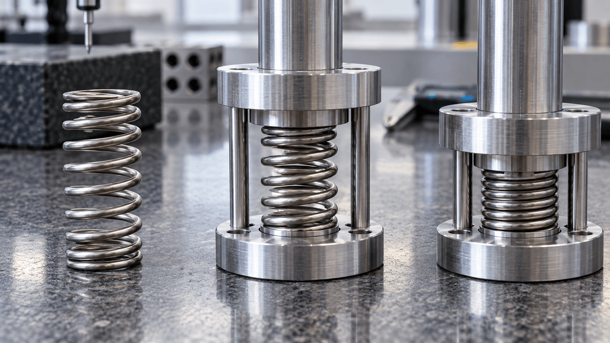
- Spring type, alloy code, wire diameter, surface, and delivery condition.
- Outside or mean diameter, active coils, total coils, pitch, and winding direction.
- Cold and hot free length with measurement temperatures.
- Solid height or maximum extension plus mechanical stop margin.
- Installed length, preload, target force, stroke, and return-force curve.
- End geometry, orientation, attachment, guide condition, and side-load limit.
- Active Af, stabilization sequence, functional test, and cycle-drift limits.
A useful niti coil spring drawing describes the installed mechanism, not just the loose spring. Free length establishes the reference, solid height protects the structure, and preload selects the working point. Together with force-stroke and temperature data, those fields give the supplier a testable target and the designer a predictable component.