

A nitinol guidewire may be sold by its finished outside diameter, but the core that controls support and flexibility often changes along its length. Tapers, flats, ground sections, distal shapes, coils, jackets, and bonded joints convert one piece of NiTi into a mechanical profile. Ordering only a nominal core diameter leaves the most important transitions undefined.
GEE SMA supplies guidewire-relevant NiTi raw material rather than making an automatic finished-device claim. Product notes list guidewire wire from 0.05 mm [0.002 in.] and identify 0.20 to 0.90 mm [0.008 to 0.035 in.] as a frequently requested range. Its superelastic wire options include multiple alloy codes, delivery conditions, and surface finishes that can serve as inputs to an OEM's validated guidewire design.
Begin With the Finished Performance Zones
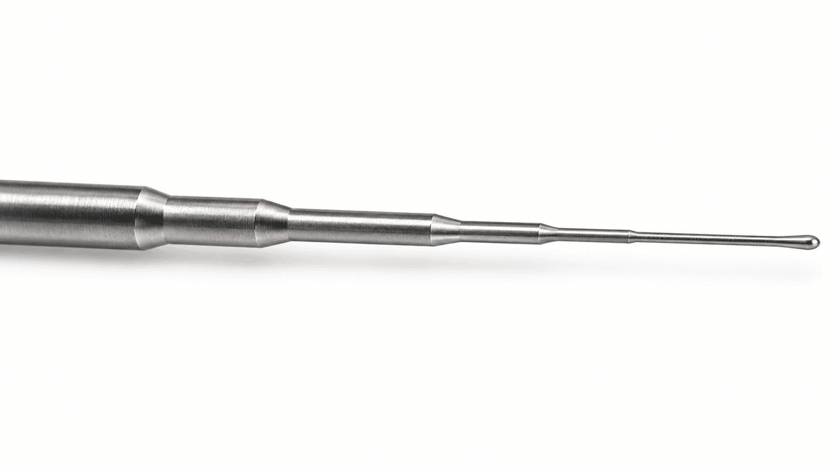
Divide the intended guidewire into proximal support, transition, distal navigation, and tip zones. For each zone, define the required bending stiffness, torque response, recovery, kink resistance, shape retention, radiopacity strategy, coating or jacket interface, and connection to neighboring components. These functions lead to a core profile more reliably than choosing one diameter first.
GEE SMA's guidewire material behavior fits designs that need recoverable flexibility, but the final torque, trackability, and tip behavior belong to the complete guidewire assembly.
Taper Length Controls How Stiffness Changes
Bending stiffness is highly sensitive to cross-section, so a small diameter reduction can create a large mechanical change. A short abrupt taper may localize bending and strain. A longer gradual taper can spread curvature but consumes more core length. Multiple tapers or flattened sections can create a deliberately staged response.
The drawing should show start and end diameters, transition length, profile tolerance, blend radii, surface requirements, and datums. Specify how the taper is made and inspected. Centerless grinding, laser processing, and mechanical forming leave different surface and residual-stress histories, which should be represented in fatigue and recovery tests.
Alloy Code Sets the Starting Mechanical Window
GEE SMA product notes list SE510, SE508, SE508 ELI, LSE5065, LSE507 ELI, and a low-temperature chromium-containing grade among superelastic wire options. SE508 and SE508 ELI are identified as common starting points for guidewire development, while other grades can shift plateau stress, flexibility, inclusion expectations, or low-temperature behavior.
These supplier designations do not replace test data. Compare candidate grades at the use temperature and after the actual grinding, straightening, heat-treatment, and surface route. GEE SMA's alloy, surface, and straightness controls keep the incoming material state connected to later core processing.
Straightness and Residual Curvature Affect Assembly
A wire can meet diameter tolerance and still create feeding, grinding, joining, or distal-shape problems because of coil set or residual curvature. Specify the straightness method, support condition, gauge length, and acceptance limit that matter to the equipment. Cold-drawn and straight-annealed wire should not be treated as interchangeable process inputs.
Product notes describe both conditions by request. Cold-drawn wire preserves downstream heat-treatment freedom; straight-annealed wire arrives with a defined straightened thermal history. GEE SMA's delivery-condition decisions help buyers state who owns the functional heat treatment before profile grinding and assembly.
Surface Requirements Change Along the Core
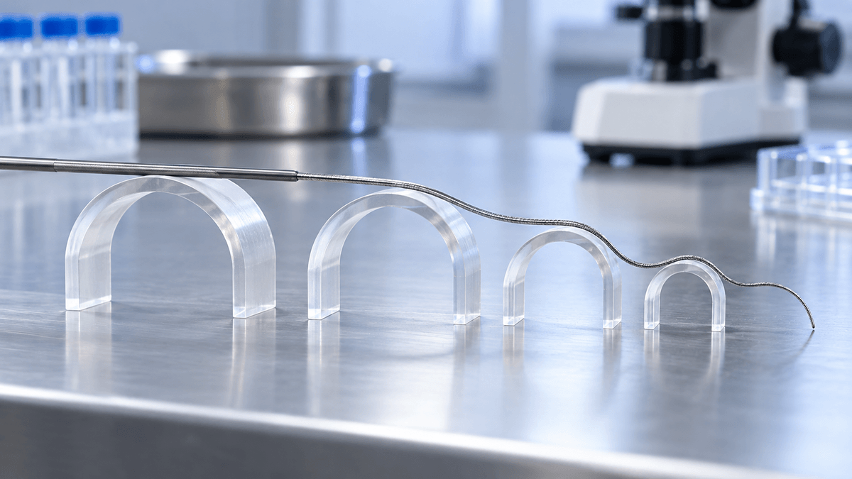
Black oxide, light oxide, and mechanically polished starting surfaces can suit different process plans. Grinding exposes fresh material in selected zones. Joining can add heat tint or local damage. Coatings and polymer jackets introduce adhesion and cleanliness needs. A single appearance requirement for the whole wire may therefore be insufficient.
Define surface state by zone and by process stage. Inspect transition blends, ground distal regions, attachment points, and any exposed finished surface. GEE SMA's surface-finish capability supports different starting routes, while the device manufacturer remains responsible for the final surface and biological evaluation.
Joints and Tips Need Separate Evidence
A complete guidewire can include coils, marker elements, polymer covers, adhesives, welds, soldered or brazed features, and shaped tips. Each joint can change stiffness, corrosion behavior, tensile integrity, and fatigue. The parent NiTi certificate cannot qualify those interfaces.
ISO 11070:2014 covers sterile single-use intravascular introducers, dilators, and guidewires and includes requirements related to surface, corrosion resistance, size designation, and guidewire performance. Apply the relevant finished-device tests to production-representative assemblies. FDA nitinol guidance also emphasizes that processing and final configuration affect the evidence needed for a device.
Build a Core-to-Device Verification Ladder
- Incoming wire: identity, diameter, straightness, surface, Active Af, and ASTM F2516 response at the agreed temperature.
- Ground core: profile dimensions, blend quality, surface condition, recovery, and local bend response.
- Subassembly: joint integrity, coating or jacket adhesion, torque transfer, and tip-shape consistency.
- Finished guidewire: dimensional, surface, tensile, corrosion, torque, trackability, kink, fatigue, packaging, and sterilization evidence as applicable.
- Production lots: traceability from incoming wire through core processing and final release.
A nitinol guidewire core should be purchased as a controlled mechanical profile. When alloy, diameter transitions, straightness, surface, and joining zones are defined together, the finished-device team can connect raw-material evidence to the flexibility and support it intends to validate.